Accuracy>99%

Safe & reliable standard:
9 V battery
PC connected for data transfer
Principle of measurements with both sets is the same for both cable sets and is illustrated by the figure and can is demonstrated in the tutorial on our YouTube channel below :
AB MN
The complete scheme of dipole-dipole manual protocol is provided as Excel workbook on USB drive to all our customers. You can also download that Excel file attached to this page http://landviser.net/webfm_send/258 (need to register).
The detail description below covers step-by-step protocol to conduct dense (~0.5 m resolution) measurements down to ~14 m depth and 50 m long. The profile can continue indefinitely to the right, as shown in Excel file. Different depths and resolutions are possible by modification of this basic protocol, per request we can develop custom protocols for you (info@landviser.net ).
This protocol is designed that whole set can be saved into LandMapper’s memory (stores 1000 data points), downloaded to PC, recalculated in Excel workbook and re-formatted for Interpretation of data in RES2DINV software (see DIY for demo version of software http://www.landviser.net/node/232 ).
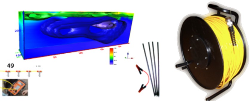
This protocol was tested by several groups of archeologists and is most suitable for detecting relatively large burial places and shallow caves. The method can help to pinpoint areas of very low resistivity (i.e. metal objects) of rectangular shape, for example as on the figure below.

Field procedure
Hammer electrodes (nails) in a straight line one meter apart. You will be making series of measurements with AB (current) electrodes planted at the beginning of the line and moving MN farther apart to reach deeper.
We refer to size of dipoles (distance between AB or MN electrodes) as “a” and during measurement protocol we will move dipole MN farther to the right from dipole AB “n” times. In this setup there will be three levels of the measurements, for different sizes of dipoles:
Level 1 – AB=MN= 1 m (measure at each electrode)
Level 2 – AB=MN= 3 m (skipping some electrodes)
Level 3 – AB=MN= 6 m (skipping some electrodes)
Level 1
Electrodes are numbered from left to right starting with “0”. For the first measurement connect electrodes #0 and #1 with alligator clips on the red wires and push banana plugs on the AB terminals of LandMapper. In the same way connect electrodes #2 and #3 to MN terminals of LandMapper using black wires. Take first measurement of electrical resistivity with LandMapper. For the next measurement (marked by “1” diagonally) move MN electrodes to #3 and #4. Note, that you can just move one alligator clip, from electrode #2 to #4, i.e. you can flip-flop M and N electrodes in dipole, this will not affect measurements. Refer to the picture below:

You should not exceed total length in any combination (from A to N electrode) to more than 7*a in order to keep good signal-to-noise ratio of the system. Therefore, after completing six moves of MN dipole, move AB dipole to electrodes #1 and #2 and repeat six measurements moving MN electrodes in the similar manner (six measurements marked “2” on the picture above). Twenty eight sets of six measurements complete Level 1 set of measurements.
Level 1 measurements cover approximately 2.5 meter depth.
Level 2
In order to go deeper, we will increase the size of dipole to AB=MN=3 m. Connect AB electrodes to #0 and #3 nails. Connect MN to electrodes to #6 and #9. Continue in the same way as for Level 1, moving MN electrodes at one meter steps to the rights (eleven diagonal measurements marked by green numbers, starting with “29”. Then move AB electrodes to #1 and #4 (detail instructions below).

Level 3
Increase dipole size one more time to AB=MN=6 m. Connect AB electrodes to #0 and #6 nails. Connect MN to electrodes to #18 and #24. Continue in the same way as for Levels 1 and 2, moving MN electrodes at one meter steps to the right (eighteen diagonal measurements marked by red numbers, starting with “57”. Then move AB electrodes to #1 and #7 and MN electrodes to #19 and #25 (detail instructions below).

After completing all measurements listed in Excel file for levels 1, 2 and 3 you will have 980 data points stored in LandMapper’s memory and about to reach a limit of the memory. Download data to laptop and paste them into ERM-data_in worksheet in first three columns (separate data from cell number and K0 indicators using Excel Data function “Text to Columns”). Make sure the resistivity values correspond to the four-electrode combinations (electrode distances from the origin in meters) they were taken on in the next four columns. For example, if you took several measurements at the same combination or skipped a, adjust worksheet accordingly.

The worksheet will recalculate respective geometric coefficient and resistivity values as well as put data in last four columns to be copied then into the last worksheet – RES2DINV_data. Before you do that, check Min/Max statistics on top of ERM-data sheet to check for typos (zero resistivity) or very high resistivities (bad connection with electrodes). Those bad data can be eliminated before importing into RES2DINV for interpretation, or cleaned directly in the software.

Refer to the RES2DINV file format description and to website:
· Input data format for any array – http://www.landviser.net/node/265
· Running resistivity inversion modeling in RES2DINV software – http://www.landviser.net/node/457
After downloading data into Excel file, clean LandMapper memory and start new profile or continue the same profile in the right direction indefinitely, see detail instructions in Excel file.